

Scan to BIM automation turns a registered, classified point cloud into BIM elements whose geometry and parameters come from the scan itself. Walls, slabs and floors automate well today, doors, columns and stairs need review, and MEP and ornament still need a modeller. A useful automated model records what it measured and what it assumed.
| What it is | Turning a registered, classified point cloud into IFC elements with geometry and parameters measured from the scan |
| What you decide | Which elements to automate, at which LOD and information need, and how the model proves each number |
| Standards it touches | IFC4 (ISO 16739-1), the BIMForum LOD Specification, EN 17412-1 Level of Information Need, the GSA BIM Guide for 3D Imaging |
| Worked example | Three office walls measured at 13.78, 12.59 and 14.87 cm on S3DIS and written as IFC4, in about 1.3 s on a CPU |
| Level | BIM managers, surveyors, owners and R&D leads. Readable without writing any code. |
On one scanned office, a script measured three walls at 13.78, 12.59 and 14.87 cm in about 1.3 s, and wrote the south wall, with no scanned room behind it, as NOTDEFINED instead of guessing it was a partition. Walls, slabs and floors automate today; the part no button does for you is honesty about which values were measured, and that is the line to write into your brief.
Come and sit on the buyer’s side of the table with me for a while. I want to show you what a scan to BIM button really automates, what really sets the bill, how to check the model that lands in your inbox, and who should own the pipeline behind it. There is a lot of useful material in here, so take your time.
- What Scan to BIM Automation Means in Practice
- The Scan to BIM Workflow From Registered Cloud to IFC
- Which BIM Elements Scan to BIM Automation Handles Today
- How LOD and LOIN Decide the Cost of a Scan to BIM Job
- Measured Parameters Versus Library Defaults in As-Built BIM
- How to Check an Automated Scan to BIM Model
- Choosing Scan to BIM Software or Building Your Own
- Where Scan to BIM Feeds the Building Digital Twin
- Own Your Scan to BIM Automation Pipeline
- Frequently Asked Questions About Scan to BIM Automation
My first startup, straight after my engineering diploma, failed because it started from the technology instead of the problem. Scan to BIM buyers repeat that mistake when they buy the button before they name the question the model has to answer.
The button does close part of the gap between a point cloud and a design model. Which part, and how you would know, is what this guide is about.
What Hooke Teaches Point Cloud Modelling
I like to know where a habit comes from before I trust it, so I hunted for the oldest scan to BIM brief on record. It is more than 350 years old, and there is no scanner in it.
In March 1667, six months after the Great Fire, the City of London’s Court of Common Council sent three surveyors, Robert Hooke, Peter Mills and Edward Jerman, to measure the burnt plots before anyone built on them again. Owners had their foundations staked out, and by the end of 1671 about 95 percent of them had been, according to Michael Cooper’s history of Hooke’s survey work, A More Beautiful City.
The grand replanning schemes went nowhere. London came back on its existing property divisions, rebuilt on a record of what had stood. I find that oddly comforting, because it is exactly the order a scan to BIM job should respect: existing conditions first, design second, and a measurement nobody can argue with in between.
Three and a half centuries later, the measuring still comes first, and it keeps getting faster: on 14 September 2026 NavVis introduced the VLX 4, a scanner you wear that the company says reaches a native 3 mm resolution while you walk, aimed at LOD350+ scan to BIM. That is the vendor’s own claim with no independent test yet, so I would check it against a tripod station before signing a drawing off it.
Here is what you will be able to do by the end
- Name which BIM element classes a scan can model on its own today and which still need a person
- Read a scan to BIM quote through LOD and LOIN, so you know what you are paying to have measured
- Tell a measured wall from a library default by opening the IFC file
- Run five acceptance checks on any automated as-built model before it reaches design
- Decide between a vendor plug-in, a service bureau and your own pipeline with the right questions
What Scan to BIM Automation Means in Practice
Scan to BIM automation is a phrase vendors and surveyors use for very different things, so before any software enters the picture, I want to pin it down with you.
Scan to BIM automation means software, rather than a modeller, decides what each part of a point cloud is and writes it as a typed BIM element with measured dimensions. The input is a registered scan of an existing building. The output is an as-built model, usually IFC or a native authoring file, where a wall is an IfcWall with a thickness, a height and a storey.
That definition sounds simple, and the trouble hides in one word: decides. A modeller tracing walls over a cloud in an authoring tool is doing scan to BIM, but nothing about it is automated. A plug-in that fits planes and asks you to confirm each one is partly automated. A pipeline that runs unattended from scan to IFC, and tells you where it was unsure, is the real thing.
Whenever somebody asks me how old this problem really is, I send them to the same two papers.
The research literature has chased that last version for over fifteen years. Tang and colleagues mapped the problem in a 2010 review in Automation in Construction (DOI 10.1016/j.autcon.2010.06.007), and Ochmann, Vock and Klein showed fully volumetric reconstruction of walls and rooms from oriented point clouds in the ISPRS Journal of Photogrammetry and Remote Sensing in 2019 (DOI 10.1016/j.isprsjprs.2019.03.017).
None of that works without the step before modelling: every point needs a class. If you want that Understand stage in depth, the point cloud segmentation and clustering guide covers it, and the indoor 3D shape detection tutorial shows the plane fitting that sits under every automated wall. The deliverable side (which format carries what, and how measured accuracy differs from drawn accuracy) belongs to the point cloud to CAD guide, the parent of this one.
🪐 System Thinking Note: Scan to BIM sits in the middle of a four-step chain I keep coming back to: capture, understand, deliver, act. The scan is capture, classes and walls are understand, the IFC is deliver, and the decision someone makes with it (a quote, a design, an audit) is act. On the S3DIS office used below, about 16 percent of the scan is wall, and every downstream number leans on that sixth.
The Scan to BIM Workflow From Registered Cloud to IFC
The scan to BIM workflow carries an old idea I keep returning to: displace what we do in the field to the office. The eight stages below are what that idea looks like once you write it down.
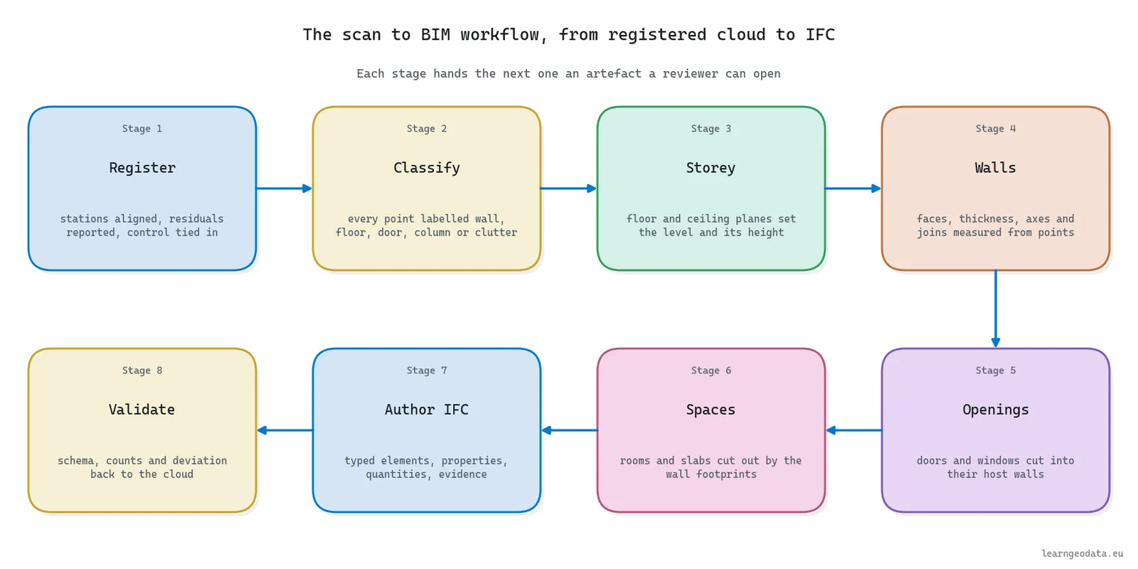
The scan to BIM workflow runs in eight stages, and an automated pipeline still has to perform every one of them, whether a person sees it or not.
- Register the stations and report residuals, with control tied in where the job needs real coordinates
- Classify every point as wall, floor, ceiling, door, window, column, furniture or clutter
- Set the storey from the floor and ceiling planes, which also levels the scan
- Model the walls: faces, thickness, axes, and the joins at corners and T’s
- Cut doors and windows into their host walls
- Derive spaces and slabs from the wall footprints
- Author the IFC: typed elements, property sets, quantities and the evidence behind them
- Validate against the schema, the agreed scope and the points themselves
On a manual job, stages 4 to 7 eat the budget, because a modeller traces and types every element by hand. On an automated one, the machine does those in seconds, and the human time moves to stages 1, 2 and 8: making sure the input is trustworthy and the output is checked.




Neurones 3D, the application I build, splits that chain into fifteen recorded stages on this office. Its explainer run reports 9 walls, 3 rooms, 6 doors and windows and 0 IFC schema errors in a 1.1 s run, and it handles the whole Area 1 floor of S3DIS in 17 s. Those are Neurones 3D’s own figures on that dataset, quoted, not a benchmark against anyone.
🦚 Florent’s Note: Honestly, the speed number is the least interesting thing in that paragraph. What matters is where the human hours go. When the walls take 1 second instead of 1 day, the expensive person in the loop stops drawing and starts checking, and checking is a far better use of a senior surveyor than tracing a partition.
Which BIM Elements Scan to BIM Automation Handles Today
Scan to BIM automation is uneven across element types, and I would rather be plain about the limits up front. Some elements are close to solved and some are nowhere near.
Scan to BIM automation handles planar, well-scanned elements reliably today: walls seen from both sides, floor slabs and ceilings. Elements defined by a gap or a profile (doors, windows, columns, stairs) automate as proposals a person confirms. MEP runs, ornament and anything inside a wall still need a modeller.
Here is the element-by-element view I would hand to anyone writing a scan to BIM brief.
| Element class | Automation level today | Typical failure | What a person still checks |
|---|---|---|---|
| Walls (planar, both faces scanned) | High | one face hidden by furniture, so no thickness | thickness source, joins at corners |
| Floors, slabs, ceilings | High | ceiling hidden above services or suspended tiles | level and slab edge |
| Doors and windows | Medium | a gap in clutter looks like an opening | type, swing, sill height |
| Columns and beams | Medium | columns buried in walls go unseen | section and whether it is structural |
| Stairs | Medium | flights and landings split or merged | riser count and headroom |
| MEP runs and fittings | Low | thin, cluttered, partly above ceilings | everything |
| Ornament and heritage detail | Low | no library type fits a free-form surface | everything |
| Wall build-up and materials | None from a scan | the laser never enters the wall | layers, from drawings or a survey hole |
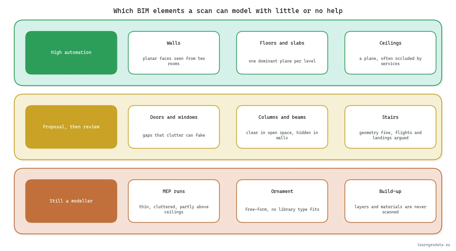
Walls sit at the top for a geometric reason worth understanding. A partition scanned from two rooms leaves two parallel sheets of points, and those sheets pile up into sharp peaks when you count points across the wall. Find the two peaks, pair them, and the gap is the thickness, with no learned model anywhere.
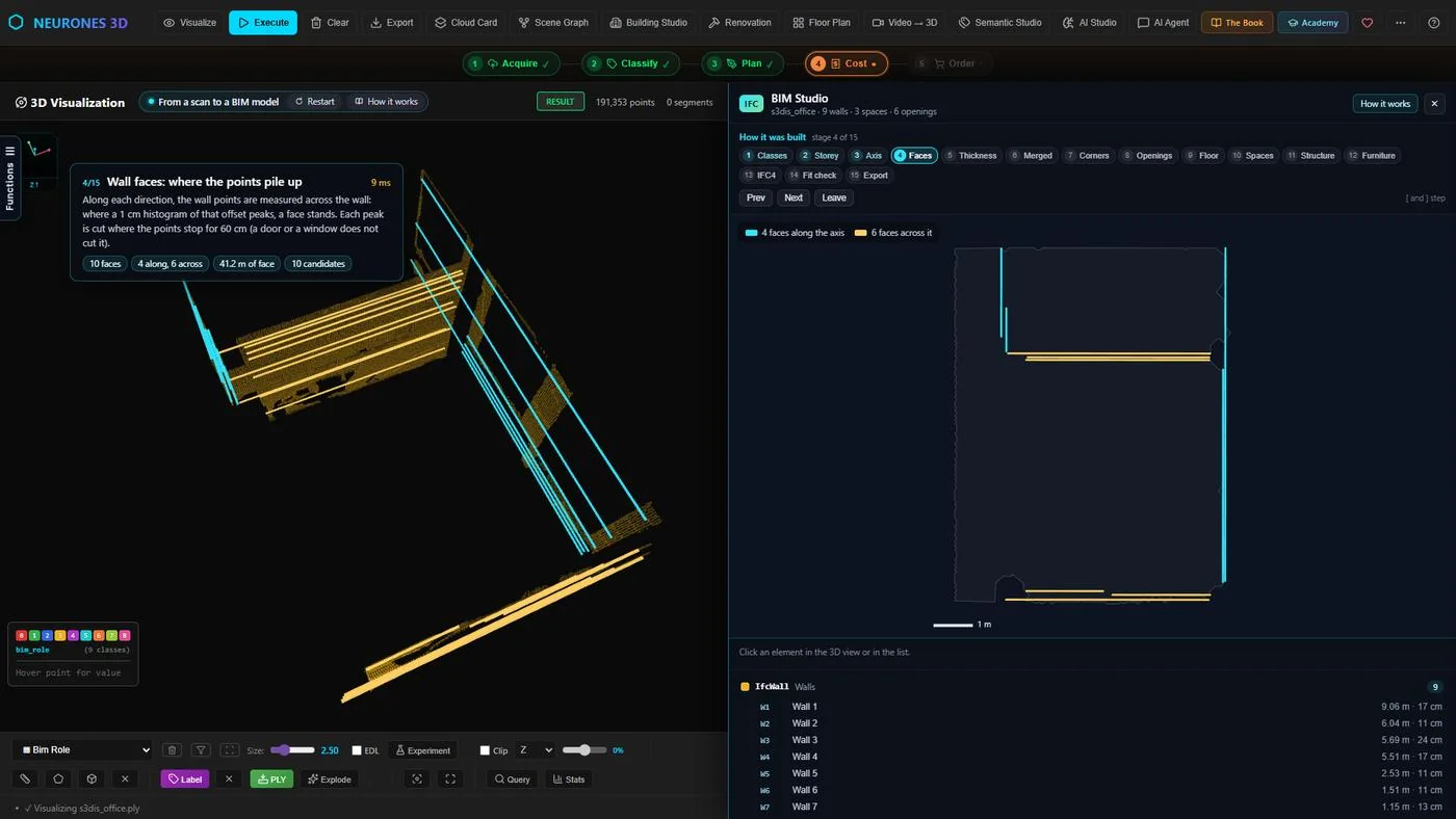
That same reasoning tells you where it breaks. A wall seen from one side only has a face, not a thickness. On the S3DIS office, 9 faces gave 3 measured walls; the rest bordered windows or unscanned space.
🦥 Geeky Note: If a scan to BIM tool cannot tell you how many of its walls were measured from two faces and how many got a default, ask for it in writing. On the office below the answer is 3 measured walls out of 9 faces. Neurones 3D gives the one-sided walls a stated default (the median of the measured ones) and writes that it did so into the IFC.
How LOD and LOIN Decide the Cost of a Scan to BIM Job
LOD and LOIN read like a standards committee wrote them, and one did. They are also where the price of a scan to BIM job gets decided, so it repays ten minutes.
LOD and LOIN decide the cost of a scan to BIM job because together they fix how much has to be measured, not merely drawn. LOD sets how developed each element’s geometry must be. LOIN sets what information each element must carry, for whom and for which decision.
When I want to know what a level of development actually promises, I skip the vendor slides and open the specification itself.
The BIMForum LOD Specification is the reference many US contracts cite for geometry. LOD 200 is approximate size, shape and location; LOD 300 is specific size, shape, location and orientation; LOD 350 adds the interfaces with other elements; LOD 400 adds what fabrication needs. For an as-built scan to BIM model, LOD 300 is where automation earns its keep, because specific size and location are exactly what a scan measures.
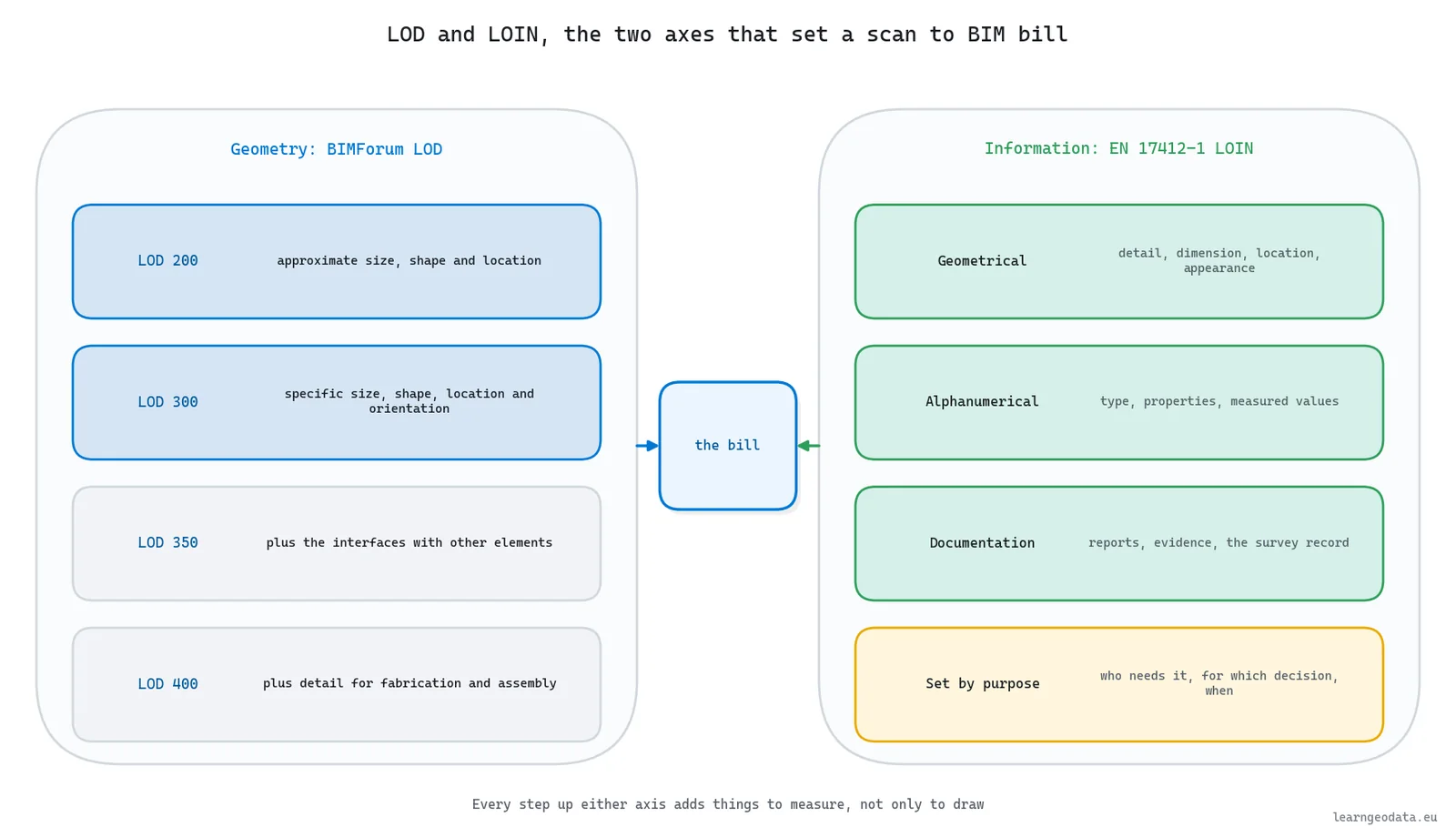
The European half took me longer to track down, because it sits in a standard with a very dry title. In Europe the information side has its own standard: EN 17412-1 (2020) defines the Level of Information Need through three kinds of information, geometrical, alphanumerical and documentation, each set by a purpose, an actor and a delivery milestone. Its point is plain and useful: the model should carry what the next decision needs, and nothing it does not.
No prices here, because they vary too much by market to quote honestly, but the drivers of the bill are stable:
- the element classes in scope, since each step down the automation table adds modeller hours
- the LOD per class, since LOD 350 joins and LOD 400 detail are mostly human work
- the alphanumerical fields per element, especially any that a scan cannot see (fire rating, material, build-up)
- occlusion, because every element hidden behind furniture or services becomes an assumption someone has to sign
- the acceptance checks you require, since a check you do not ask for is a check nobody runs
🪐 System Thinking Note: BIMForum’s specification describes LOD 500 as field verification and says that is not a step up in geometry or information, so it does not define or illustrate it. Writing “LOD 500 as-built” into a scan to BIM brief therefore buys you nothing measurable. Name the LOD per element class, then name the tolerance separately.
Measured Parameters Versus Library Defaults in As-Built BIM
If I were buying a scan to BIM model, the difference between measured parameters and library defaults is what I would read twice. Everything else in the guide leans on it.
Measured parameters are values read from the scan for one specific element; library defaults are values copied from a type catalogue because nothing was measured. In an as-built BIM model the two look identical in the viewer, and that is the problem. A wall typed “Generic 200 mm” is a guess with a GUID.
Hooke’s surveyors did not stake out a plot from a pattern book; they measured the one that stood there. An as-built model owes its user the same courtesy, element by element.
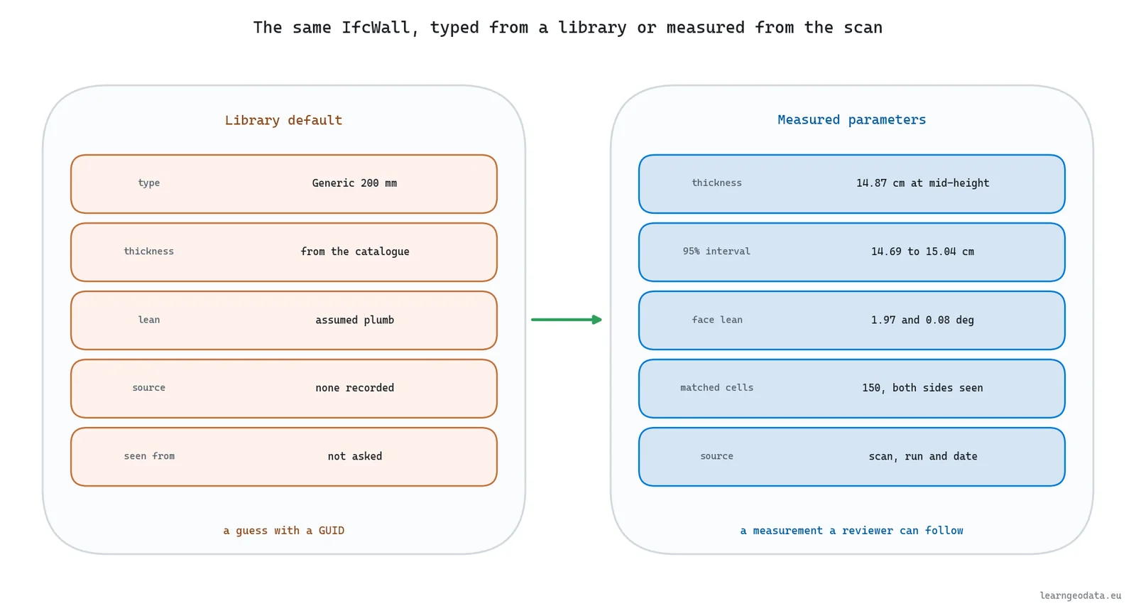
Wall thickness is the cleanest worked case I know, and I ran it on a public dataset so you can check me.

On one office of the S3DIS dataset (Armeni et al., CVPR 2016), the code from my scan to BIM tutorial reads the classified scan, finds 9 wall faces, rejects one false pair and measures three walls nobody touched, at mid-height, at 13.78, 12.59 and 14.87 cm. Measuring and exporting all three as IFC4 walls is done in about 1.3 s, on an ordinary CPU.
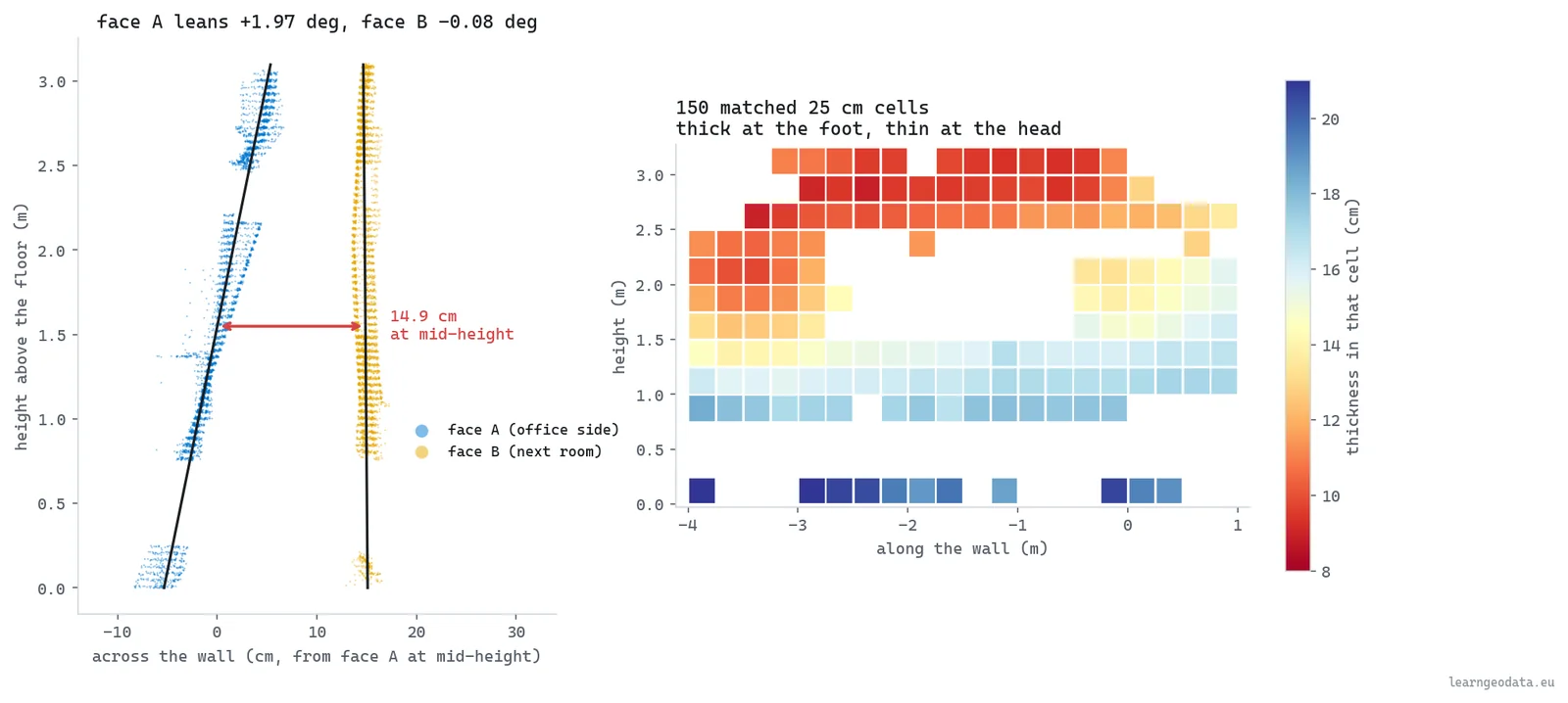
What came with the number matters more than the number. The longest wall reads 19.69 cm in its lowest band and 9.64 cm above 3 m, because one face leans 1.97 degrees while the other stands within 0.08 degrees of plumb. So “14.87 cm” describes mid-height only; in this scan the wall simply has no single thickness, and the file says so.
The word “says” needs care, because a property set says nothing unless somebody reads it. So here is the one snippet in this guide, and it is not there to teach the method: it opens the delivered IFC with IfcOpenShell and prints what the file claims about each wall.
import ifcopenshell
import ifcopenshell.util.element as ue

model = ifcopenshell.open("measured_partitions.ifc")
for wall in model.by_type("IfcWall"):
    ps = ue.get_psets(wall)
    qto, ev = ps["Qto_WallBaseQuantities"], ps.get("Scan_Evidence", {})
    print(f'{wall.Name:8s} width {qto["Width"] * 100:.2f} cm | '
          f'CI95 {ev["ThicknessCI95Low"] * 100:.2f}-{ev["ThicknessCI95High"] * 100:.2f} | '
          f'cells {ev["MatchedCells"]} | source: {ev["ThicknessSource"][:8]}')
Run against the tutorial’s output, it prints three lines: Wall 3 at 14.87 cm with a 95 percent interval of 14.69 to 15.04 cm over 150 matched cells, source “measured”. If a delivered model has no evidence set at all, that loop prints only widths, and you have learned something about your supplier in four seconds.
Get the Scan to BIM Wall Materials
If you would rather check those three walls yourself than take my word for them, the wall thickness to IFC kit has the code, its 17 tests on synthetic walls of known thickness, a preparation script that recreates the same office once you have downloaded S3DIS yourself, and the reference measured_partitions.ifc so you can compare your file with mine. The step-by-step build, face pairing included, is in the Medium tutorial; this guide stays on the decisions around it.
🌱 Growing Note: Open any as-built IFC you already own and count the IfcWall types. If a 40-room floor collapses into 2 or 3 thickness types, those walls were probably typed, not measured. On the S3DIS office, three walls gave three different measured thicknesses spread over 2.3 cm (12.59 to 14.87), a spread no catalogue would have produced.
How to Check an Automated Scan to BIM Model
A model that looks right on screen has passed zero checks so far. The good news is that the checks are boring, quick and very hard to fake.
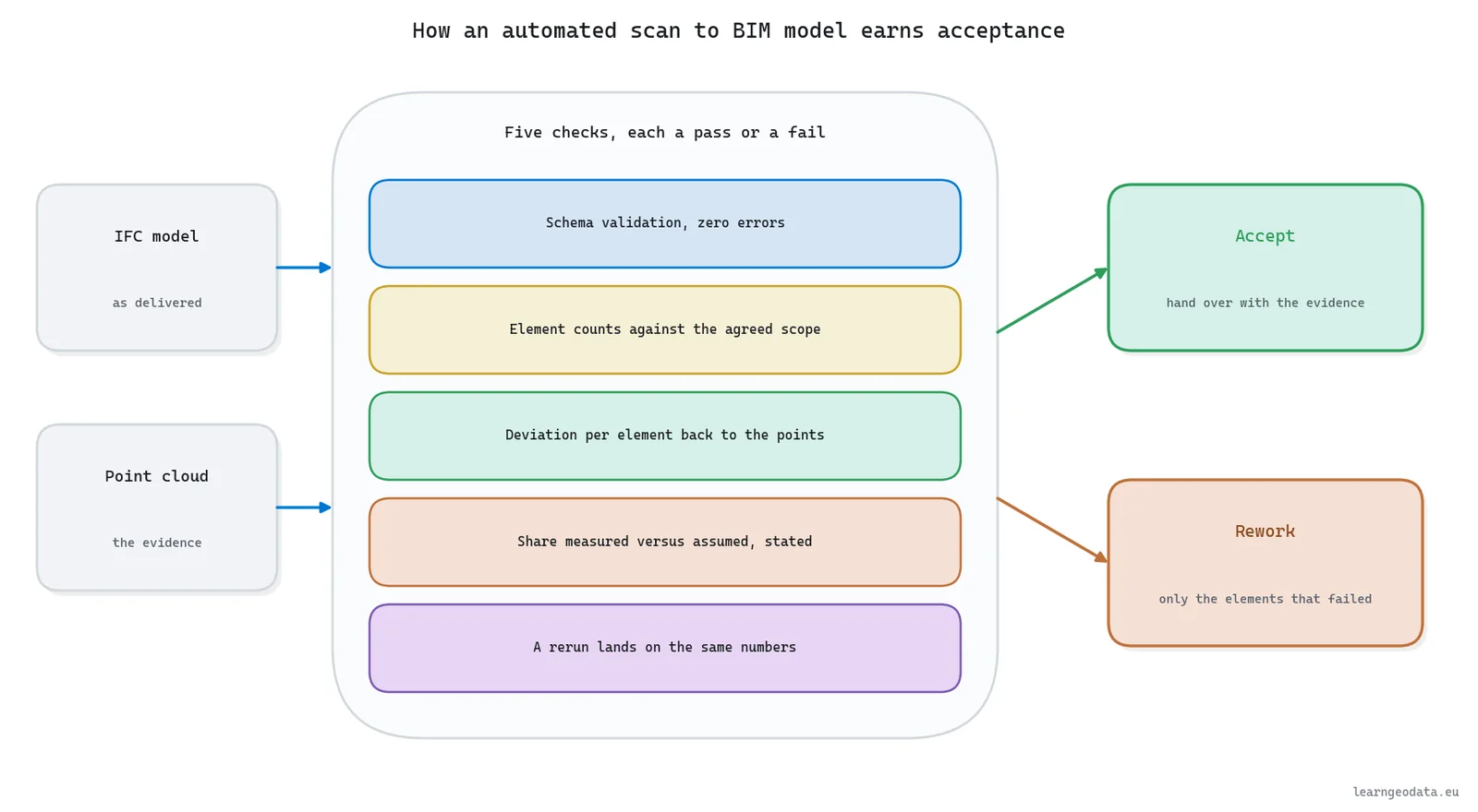
Checking an automated scan to BIM model means comparing it against three things: the IFC schema, the agreed scope, and the point cloud it came from. Run these five checks before the model reaches a design team.
- Validate the file against the IFC schema, with IfcOpenShell or the buildingSMART validation service, and expect zero errors
- Count elements per class against the scope, so a missing stair or an extra wall shows up as a number
- Measure deviation per element back to the points, and read it as a distribution, never a single average
- Report the share of elements measured versus assumed, per class
- Rerun the pipeline and confirm it lands on the same numbers
On the office, those checks come back with real numbers. The written file holds 166 entities and validates with 0 errors; the thickness read from the solid, the quantity set and the material layers match the measured value with a difference of 0.000 mm. Against the points, every face point of the short wall sits within 2 cm of its solid, while the leaning wall fits 73.7 percent within 2 cm, with a mean of 1.54 cm.
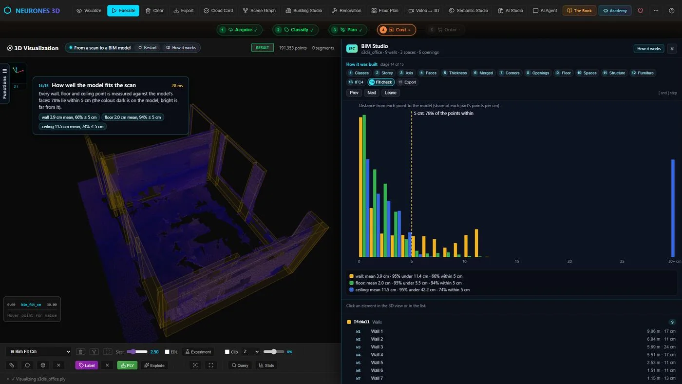
That 73.7 percent is the lean from the previous section, priced in. A vertical box cannot follow a face leaning 2 degrees, and the deviation check says exactly how much it cannot. Neurones 3D reports 78 percent of the office’s points within 5 cm of its full model, which is the same kind of honesty at whole-building scale.
The rerun check sounds dull until it saves you. Rerun as delivered and with the points shuffled three ways, the three thicknesses move by 0.0000 cm; with every coordinate rounded to 1 mm, by 0.0006 cm. A pipeline whose answer changes when the input order does is reporting noise.
Asking a laser scanning supplier for this kind of proof is not a new idea, and the earliest public brief I know that does it came from the US government in 2009.
The US General Services Administration’s BIM Guide Series 03 for 3D imaging (version 1.0, January 2009) made the same argument for laser scanning deliverables years ago: specify tolerance and minimum artifact size up front, then check the delivered data against them. For check 3, the deviation map from points to a model is worked through in my book‘s chapter on 3D data analysis.
Choosing Scan to BIM Software or Building Your Own
Choosing scan to BIM software rests on one lesson from my surveying years: know what needs automating, and never automate something that does not work manually. Whichever route you pick, that rule comes first.
Scan to BIM software comes in three routes: a vendor plug-in inside your authoring tool, a service bureau that returns a model, or a pipeline you own. Each one is the right answer for somebody, and the choice turns on who sets the method and who can explain the numbers afterwards.
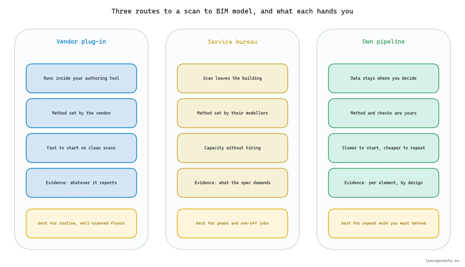
A plug-in is fastest to start on clean, routine floors. A bureau gives you capacity for peaks without hiring, at the price of the scan leaving the building and the method living in someone else’s team. Your own pipeline is slower to start and cheaper to repeat, and it is the only route where evidence per element exists because you designed it to.
Whichever route you take, ask the same five questions before you sign:
- which element classes are modelled from measurement, and which get defaults
- where each thickness, height and opening size comes from, and whether that is written into the file
- what the deviation report looks like, per element and as a distribution
- whether the deliverable is open IFC, readable without the vendor’s software
- whether a rerun of the same scan next year gives the same model
🦚 Florent’s Note: I have no interest in vendor bashing; good plug-ins save real hours. My only test is the second of those five questions. A supplier who answers “the thickness comes from the type” has told you the model is a drawing with metadata, and that is fine as long as everyone downstream knows it.
IFC matters here more than any feature list. I always check who stands behind a format before I trust a model to it, and for IFC the answer is reassuring. buildingSMART’s IFC standard, published as ISO 16739-1, is the open handoff: a model you can read with IfcOpenShell, Bonsai or any certified viewer is a model whose next use does not need your supplier’s permission.
Where Scan to BIM Feeds the Building Digital Twin
A scan to BIM model feeding a building digital twin leaves your desk and starts a second life. That second life is where cheap shortcuts come back to collect.
Scan to BIM feeds the building digital twin by turning one scan into the base every later decision reads: renovation quantities, accessibility audits, egress analysis, design checks and condition tracking. A twin built on defaulted walls inherits every default, quietly, in each of those uses.
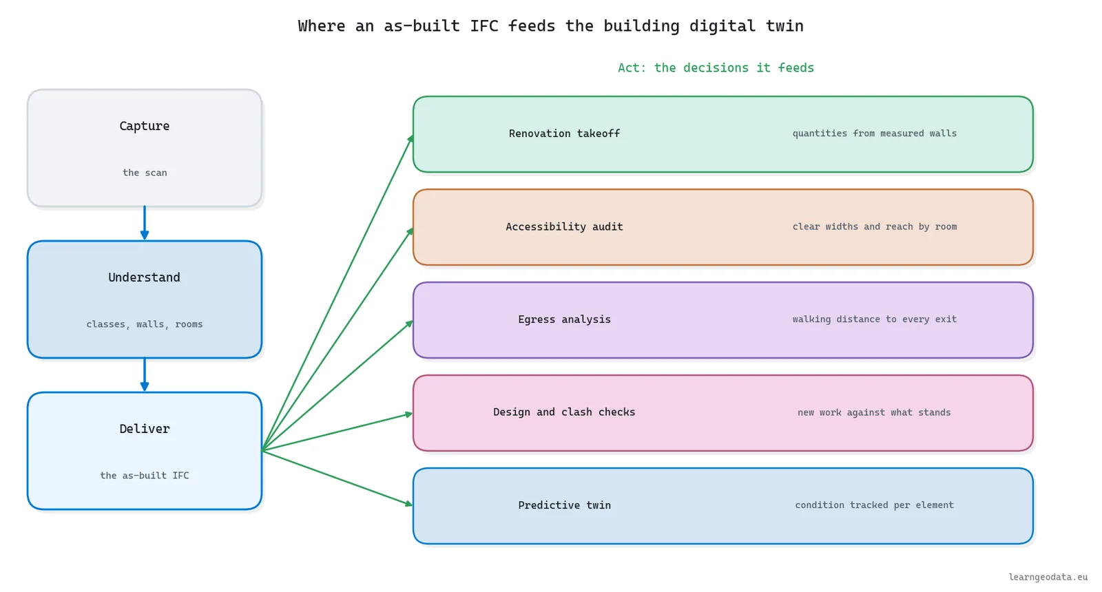
Take a renovation quote. Paintable wall area comes straight from measured wall faces, so a defaulted thickness shifts every opening reveal and every lining quantity. Take an accessibility audit: clear widths depend on where the wall faces really are, not where a 200 mm type puts them.

Further along, a predictive twin tracks condition per element over time, which only works if each element is a stable object with measured parameters and a GlobalId that survives a rerun. The predictive digital twin guide covers that forecasting side, and my NXT BLD talk on 3D spatial AI for AEC explains why I treat BIM as a feeder to a cognition stack rather than the end of the line.
🪐 System Thinking Note: Stable identifiers are the quiet hero of the twin. The tutorial’s IFC builds every GlobalId from a hash of the scan plus the element, which means a rerun on the same scan keeps every id, and re-importing the file into a BIM tool updates the 3 walls in place instead of adding 3 duplicates. Without that, every rerun breaks every link the twin had built.
Own Your Scan to BIM Automation Pipeline
Owning a scan to BIM pipeline is a trade-off, and I want to be straight about it before the last stretch. It takes more thought at the start and far less arguing at the end.
Owning your scan to BIM automation pipeline means you set the question asked, the method chosen and the checks that prove it yourself, and let an engine run them on every scan. That split is what lets you explain a number when a client asks for it.
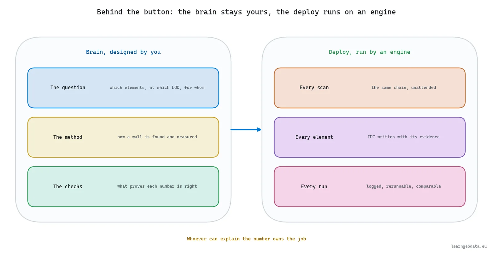
Buttons are fine until someone asks why the wall is 14.87 cm and not 20. At that moment you either know what is behind the button or you are forwarding the question to a vendor. Knowing it does not mean writing every line yourself. It means you chose the method, you set the checks, and you can open the file and point at the evidence.
Start small. Pick one floor you have already modelled by hand, run an automated wall pass on it, and compare the two models element by element. The walls where they disagree are your first acceptance test, and the ones where the automated model says “one face only” are your first honest conversation with a client.
The wall thickness to IFC kit is where I would begin: three measured walls, the tests that prove the method on known answers, and an IFC you can open tonight. The hands-on walkthrough lives in the Medium tutorial, and the book page has the plane fitting and segmentation chapters it assumes.
When you want the whole chain rather than one stage, the 3D AI Architect program covers scan to BIM alongside many other pipelines, and the Python code it gives you, plus the Neurones Science SDK, becomes the base for an application of your own. And if you would like to see the capture-to-decision idea in the app first, scan to knowledge is where Neurones 3D lives on this site.
Ask your supplier one thing before your next scan to BIM model: which walls were measured and which came from the type. On the office in this guide, the delivered file marks the south wall NOTDEFINED because no room was scanned behind it.
Frequently Asked Questions About Scan to BIM Automation
Can scan to BIM be fully automated?
Not end to end, today. Walls seen from both sides, floors and ceilings automate reliably; doors, windows, columns and stairs automate as proposals a person confirms; MEP runs, ornament and wall build-ups still need a modeller. A credible automated pipeline runs unattended and flags every element it measured, defaulted or doubted. The BIMForum LOD Specification helps scope which classes need which development.
What LOD do I need for an as-built scan to BIM model?
For an as-built model used in design, LOD 300 per the BIMForum specification is the usual target: specific size, shape, location and orientation, which is what a scan measures. Ask for LOD 350 only where interfaces matter, and pair the LOD with an information need under EN 17412-1 and a stated tolerance. The BIMForum LOD Specification defines each level.
Can a laser scan measure wall thickness?
Yes, when both faces of the wall were scanned from the rooms on either side. The two faces pile up as two density peaks, and the distance between them, compared at the same place and height, is the thickness. A wall seen from one side only cannot be measured and should be marked as assumed. The IfcOpenShell documentation shows how to write the result into IFC.
Which file format should a scan to BIM deliverable use?
Ask for open IFC, published by buildingSMART as ISO 16739-1, alongside any native authoring file. IFC carries typed elements, property sets and quantities, so measured values and their evidence travel with the model, and anyone can read it without the supplier’s software. The buildingSMART IFC page lists the current versions.
What should a scan to BIM specification include?
Name the element classes in scope, the LOD per class, the information need per element, the tolerance, and the acceptance checks: schema validation, element counts, deviation against the points, the share measured versus assumed, and rerun stability. Require that defaulted values are marked in the file. The buildingSMART validation service covers the schema check.
SEO Keywords
scan to BIM automation, scan to BIM workflow, automated BIM from point cloud, as-built BIM, LOD for scan to BIM, scan to BIM software, wall thickness from point cloud, IFC as-built model, Level of Information Need, building digital twin

