

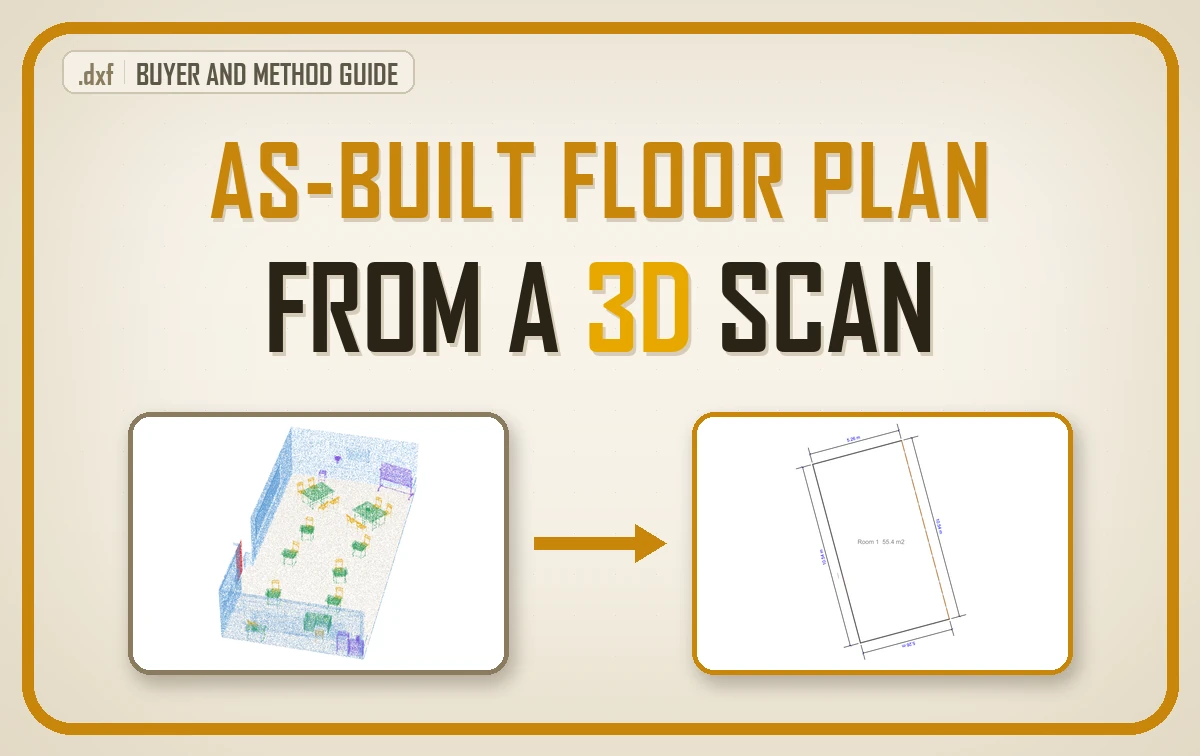
This how-to guide takes you from a first 3D scan to an as-built floor plan you can sign: a measured drawing of a building as it stands today, surveyed from its real walls. You slice the point cloud at wall height, fit each wall, export to CAD, and mark which walls were measured and which were assumed.
| What it is | A measured plan of a building as it stands now, drawn from a scan rather than from old drawings |
| What you get here | Four capture and drafting routes compared, the area standards to name, and a spec checklist for your surveyor |
| Standards it touches | IPMS: All Buildings, the RICS measured surveys standard, BOMA for offices, DXF as the open handoff |
| Worked example | A classified classroom scan turned into four walls and a 55.42 m² room |
| Level | Buyers, architects, property and facility managers, surveyors. Reading it requires no programming. |
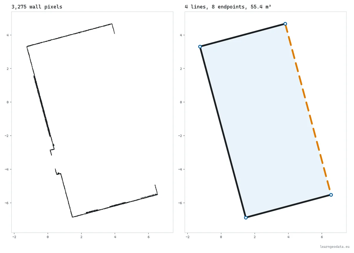
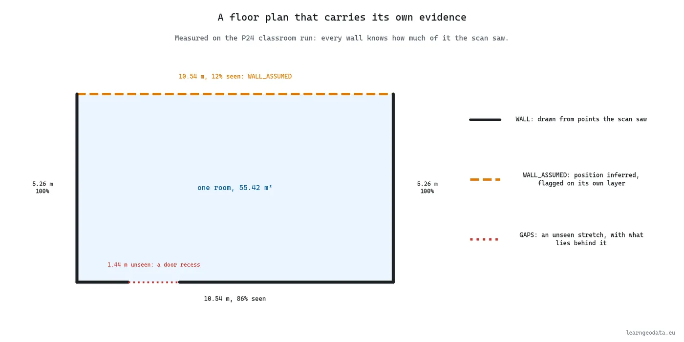
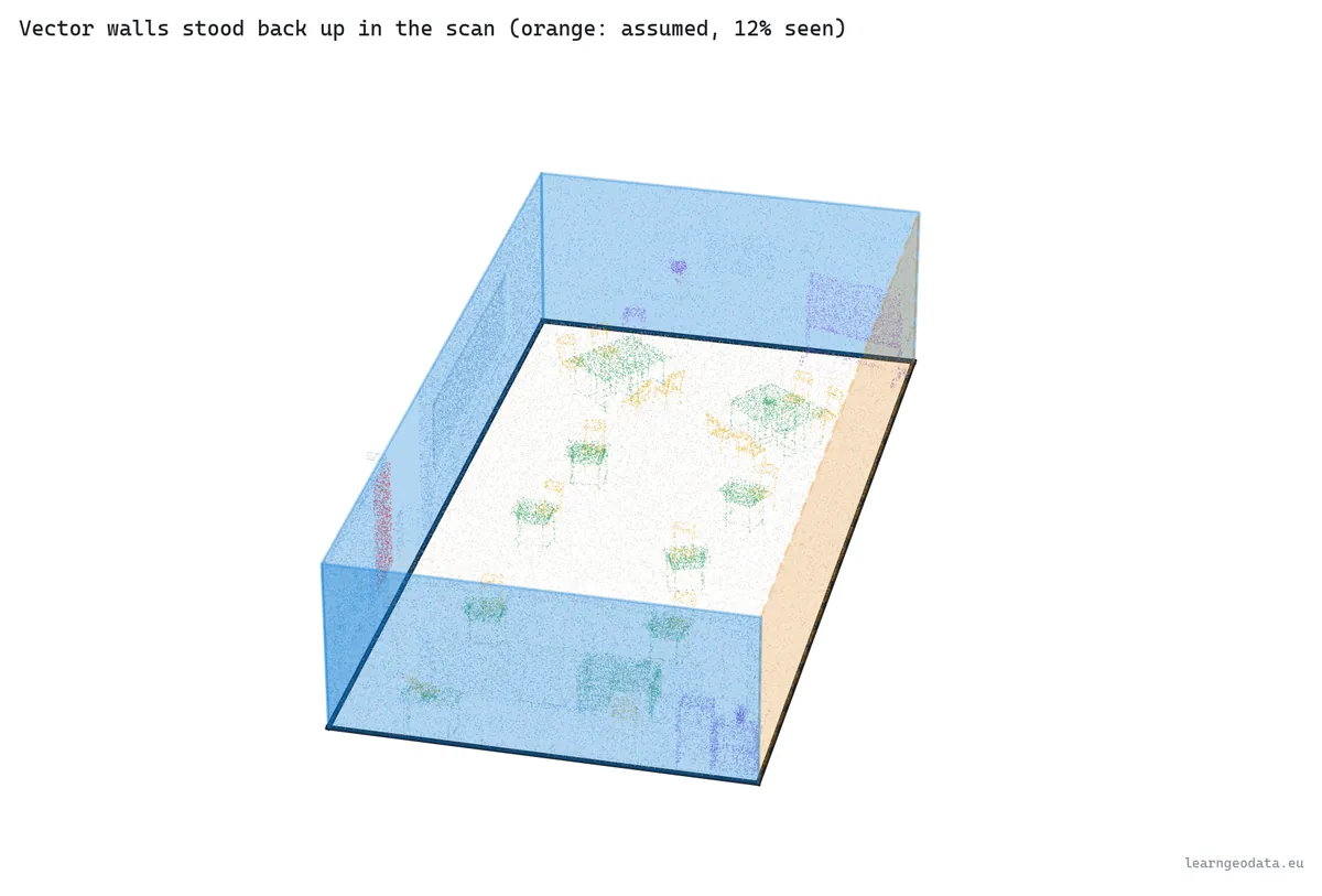
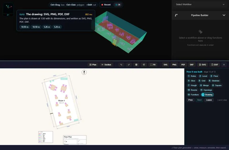
On one scanned classroom, the method returned four walls and a 55.42 m² room in under a second, and the fourth wall came out dashed because the scan saw only 12 % of it. That dashed line is the whole method in one picture.
Alright, today I want to walk you through the floor plan you can actually trust. We will look at which method to pay for, how accurate a plan from a scan really is, which area rule to name, and the one page to send your surveyor before anyone sets up a scanner.
If you have never done this, the last section shows where to get started: one room you already have a plan for. I have some good things for you in here.
- What an As-Built Floor Plan Is and Who Needs One
- Four Ways to Get an As-Built Floor Plan Compared
- How Accurate a Floor Plan From a 3D Scan Really Is
- Which Floor Area Standard Your Plan Should Follow
- What Automated Floor Plan Extraction Gets Right and Wrong
- The As-Built Floor Plan Spec to Send Your Surveyor
- From the As-Built Floor Plan to the Next Decision
- Own the Floor Plan Pipeline Instead of Ordering It Again
- Frequently Asked Questions About As-Built Floor Plans
Nearly every renovation, lease or fit-out I have been close to opens with the same email: could you send the existing plans? What comes back is usually a drawing from the original permit, redrawn twice, with a partition that moved years ago and a door nobody remembers bricking up.
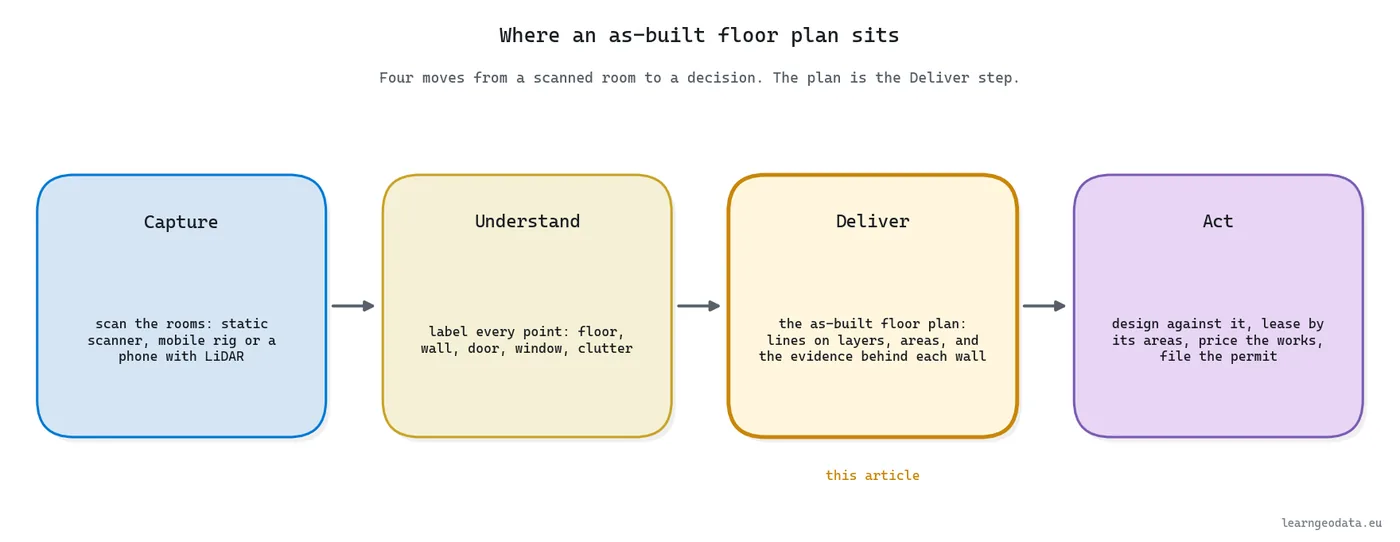
A scan fixes the “as it stands” part in an afternoon. Turning that scan into a plan people can sign is the part that needs judgement.
Nolli’s Rome and 3D Floor Plans
I went digging for where the idea of a plan that tells you where you can walk really comes from, and I found a map I have not stopped thinking about since.
In 1748 Giambattista Nolli published his plan of Rome on twelve copper plates, the result of a survey he had started in 1736. Private buildings sit in dark hatching, while public interiors such as the Pantheon and the colonnades of St Peter’s Square are left open, drawn like the streets around them (the Nolli map). He even turned the sheet to magnetic north because his bearings came from a compass, so the method sits on the page.
That is the standard I would hold any as-built floor plan to. Nolli’s plan told a reader where they could walk, and the masonry came second. A plan made from a 3D scan can go one step further and tell you which of its lines were seen by the scanner and which were filled in by somebody’s judgement.
By the end you will be able to buy and check an as-built plan with confidence
- Pick between tape, phone LiDAR, scanner plus drafter and scanner plus code for your building
- Tell measured accuracy from represented accuracy before you quote a tolerance
- Name the floor area standard so two plans of one room finally agree
- Spot where automated floor plan extraction guesses, and how a plan should admit it
- Send a one-page spec that makes the plan you receive usable on the first delivery
What an As-Built Floor Plan Is and Who Needs One
Before the methods and the prices, it helps to agree on what you are actually buying. The word gets stretched in both directions.
An as-built floor plan is a horizontal cut through a building drawn from measurements of what exists, at a stated height, in stated units, against a stated area rule. It differs from a design drawing in one way that matters: a design drawing says what somebody intended, an as-built floor plan says what somebody checked. Surveyors call the same deliverable an existing conditions survey or a measured building survey.
Who asks for one? Architects starting a renovation, property managers letting space by the square metre, contractors pricing works, and fire and access consultants who need a base. Same lines, different reasons, which is why the spec matters more than the method.
A scan on its own is not a plan: nobody can click a wall in it, ask it for an area, or put it on a layer. The plan is the reduction, a few dozen lines that somebody stands behind.
🪐 System Thinking Note: The classroom plan used as the worked example below is a 54.8 kB DXF of four walls, drawn from a scan of the entire room. That ratio is the whole job. Every point you throw away is a claim about the building, so the value of a floor plan sits in the decisions that did the throwing away, and in whether anyone wrote them down.
Four Ways to Get an As-Built Floor Plan Compared
I started as a land surveyor, scanning sites and turning them into deliverables, so this is a choice I know from the inside. None of the four routes is wrong; each one is wrong somewhere.
Four routes produce an as-built floor plan today: a tape and laser distance meter, a phone LiDAR app, a 3D scanner followed by manual drafting, and a 3D scanner followed by automated vectorization. They differ less in price than in what kind of certainty you end up holding, and in who carries the risk when a number turns out wrong.
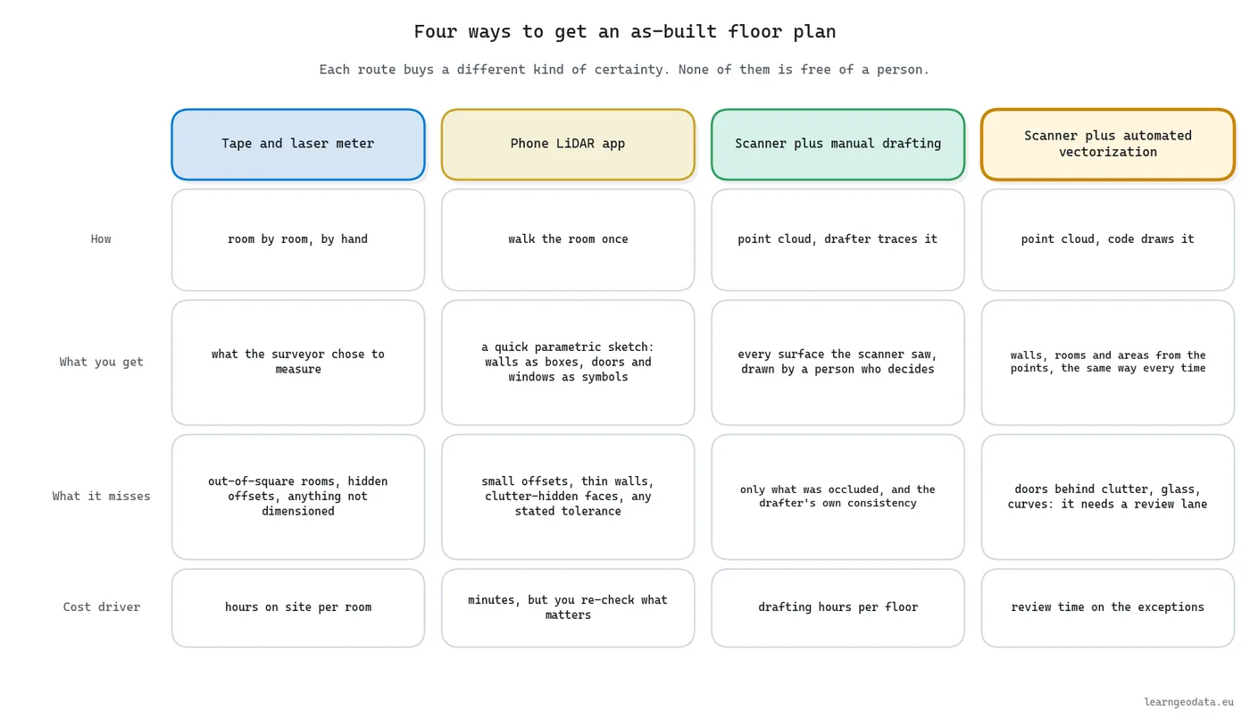
| Method | Typical deliverable | What it misses | Cost driver | When it wins |
|---|---|---|---|---|
| Tape and laser meter | hand sketch redrawn in CAD | out-of-square rooms, offsets nobody dimensioned | surveyor hours on site per room | one or two simple rooms |
| Phone LiDAR app | parametric model, walls as boxes | small offsets, thin walls, faces hidden by furniture | minutes on site, then your own checking | space planning, a quick sketch |
| Scanner plus manual drafting | CAD plan traced over the cloud | only what the scanner never saw | drafting hours per floor | complex or heritage buildings |
| Scanner plus automated vectorization | CAD plan written by code from the cloud | doors behind clutter, glass, curved walls | review time on flagged walls | repeat work, many similar floors |
The phone route deserves a fair hearing, because it has become very good at what it was built for. Apple describes RoomPlan as a framework that uses the camera and LiDAR Scanner on iPhone and iPad to build a 3D floor plan with dimensions and furniture types, exported as USD or USDZ. Read that carefully: it fits walls and objects as parametric shapes, so what you get is a model of the room, not a record of it.

The two scanner routes share the same raw evidence and split on who draws. A drafter tracing a cloud is slow and consistent with themselves; code is fast and consistent with its parameters. Neither one is automatically more honest. Honesty comes from the deliverable recording what was seen.

🦚 Florent’s Note: In the Neurones 3D explainer run, the classroom goes from scan to finished drawing in 5.4 s, with 30 furniture objects placed. The speed never impresses clients for long. What they keep asking about is the one dashed wall, which tells me where the real value of a plan lives: in the parts that admit doubt.
How Accurate a Floor Plan From a 3D Scan Really Is
I have to be honest about a limit here: no clever drawing can be more accurate than the scan it was drawn from. Everything in this section follows from that one uncomfortable fact.
A floor plan from a 3D scan carries two accuracies, and the plan can never beat the survey underneath it. Measured accuracy is how well the survey recorded the surfaces. Represented accuracy is how well the lines on the plan match those recorded surfaces after slicing, fitting, squaring and drafting. A scanner spec sheet only ever describes the first.
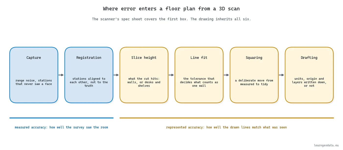
I will not re-derive the error budget here, because the point cloud to CAD guide does it properly, with the USIBD split between measured and represented accuracy and the RICS accuracy bands. What a buyer needs from it is one habit: ask for both numbers, and ask how the second one was checked.
The slice height is the step people underrate. Cut a classroom at desk height and the desks become walls. Cut it at 1.2 m and you catch whiteboards, radiators and shelving that sit proud of the wall. A good plan states the band it read walls from, so you know what was allowed to count.
🦥 Geeky Note: On the classroom run, the straight wall runs fit their points with a median RMS of 7.6 mm and a worst of 11.5 mm. Squaring the room then moved individual walls by up to 17.7 mm and closed corner gaps of up to 8.1 cm. That move is deliberate, and it is fine, but it is represented accuracy you chose, so it belongs in the handover note.
Which Floor Area Standard Your Plan Should Follow
Floor area standards sound like paperwork, and they quietly settle the arguments about a floor plan. Stay with me for a few paragraphs.
A floor area standard decides which wall face an area is measured to, and that single choice explains why two honest plans of one room disagree. Name the standard in the brief, or every party will quietly use their own. The three you will meet are IPMS, the RICS Code of Measuring Practice areas, and the BOMA standards for North American offices.
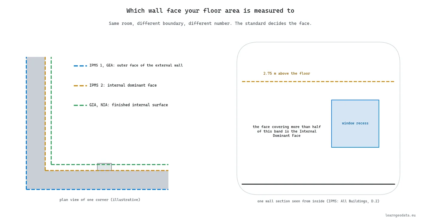
IPMS: All Buildings, published by the IPMS Coalition in January 2023, replaced the earlier asset-class versions with one standard. IPMS 1 measures to the external extent of the external walls. IPMS 2 measures internally to the Internal Dominant Face, and IPMS 3.1 and 3.2 cover areas in exclusive occupation.
The Internal Dominant Face is where a scan earns its keep. IPMS defines it as the inside surface covering more than 50 per cent of the lowest 2.75 m of each wall section, measured up from the structural floor. A tape gives you a face at one height. A scan holds the whole band, so the dominant face can be measured rather than argued about.
The same IPMS document asks that every report states the standard used, the method of measurement and the tools, the unit, the date, and whether and how the measurement was verified on site. That reporting clause is, in effect, an evidence requirement written into an area standard.
UK leases still run on the RICS terms GEA, GIA and NIA, which RICS lists beside IPMS in its measured surveys standard. US offices usually follow the ANSI/BOMA Z65.1 office standard.
🌱 Growing Note: Try this on your next scanned floor. For each external wall section, measure the share of the lowest 2.75 m that sits on the inner face versus a lining or a recess. If it is above 50 per cent, that face is your IPMS 2 boundary. One evening of work, and every lease area on the floor stops depending on who held the tape.
What Automated Floor Plan Extraction Gets Right and Wrong
Automated floor plan extraction is where the story stops being tidy. A clean drawing on screen tells you very little about how the code got there.
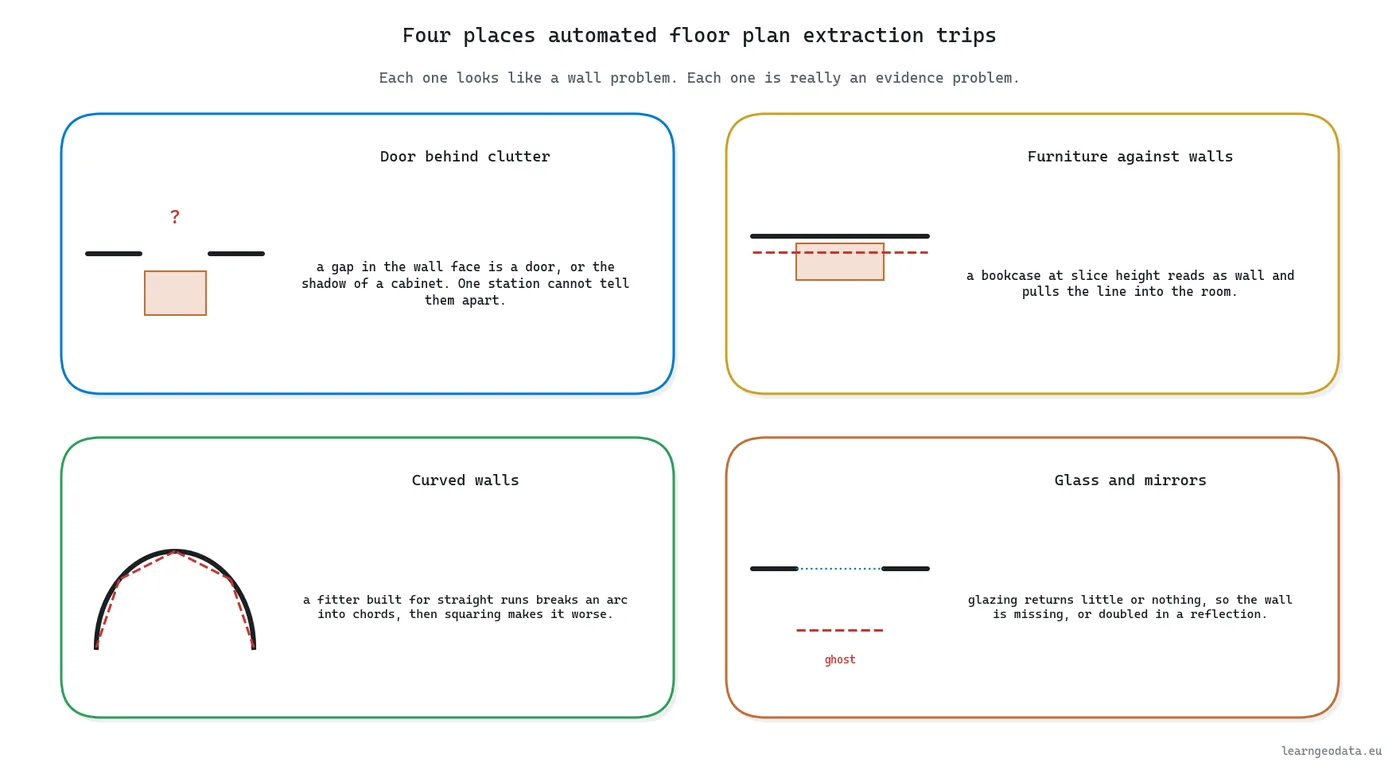
Automated floor plan extraction is reliable on long straight walls with clear evidence and unreliable wherever the scan saw something ambiguous: an opening behind furniture, clutter against a wall, a curved wall, or glass. The fair test of any automated plan is not whether it looks clean, but whether it tells you which walls it was unsure of.

The classroom run makes this concrete. A classified scan of the classroom becomes four walls, 10.54 and 5.26 m long, around one room of 55.42 m², with a 31.60 m perimeter, written to a DXF in well under a second on a laptop CPU, as measured by the tutorial’s own code.
The Door Found Behind a 3D Scan Gap
One long wall shows a 1.44 m stretch the scanner never saw. A naive extractor would either bridge it with a straight line or call it a door. The run does neither: it looks behind the gap, finds wall points sitting a median 24 cm back, which is a recess, and finds the door-class points inside it, 0.71 m wide. The Neurones 3D explainer measures the same door at 0.70 m.
The 12 Per Cent Wall on the Point Cloud Plan
The opposite long wall is the more interesting case. Across the band where walls are read, between 0.30 and 2.01 m above the floor, the scan saw only 12 per cent of its length. Yet along the skirting, wall points cover the full 10.54 m and sit 1.8 mm from the inferred line. So the position is confirmed and the height is not.
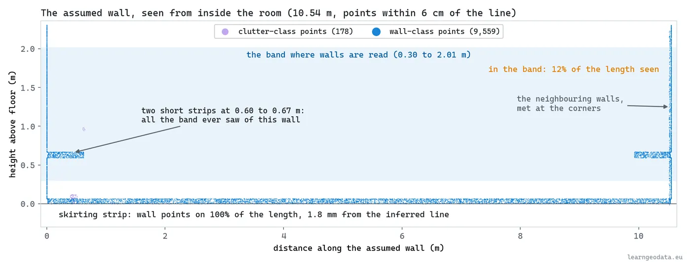
What does an honest plan do with that? It draws the wall, on its own WALL_ASSUMED layer, dashed, with its seen share and its base support stored on the entity. The architect then knows the line is right and the wall above the skirting is unverified, which could be glazing, a curtain or a surface the scanner missed.
🪐 System Thinking Note: Rotate the same classroom scan by 1 degree and the run returns a fifth wall, 1.44 m long, at the back of the door recess, while the four room walls move by no more than 2 mm. The deliverable is stable; the small pieces are not. That is the pattern I would expect from any extraction engine, so judge a tool on its room walls and read its fragments with care.

Get the materials for this floor plan. If you would rather check the classroom result than take my word for it, the scan to floor plan materials hold the script, its seventeen tests, the reference floor_plan.dxf and how to get the scan. The step-by-step tutorial on Medium builds it with you, and the code sits in the scan-to-floor-plan-dxf folder of the public 3d-data-materials repository.
The As-Built Floor Plan Spec to Send Your Surveyor
If you only keep one page from this guide, keep this one. It costs nothing to send and saves the second round of emails.
An as-built floor plan spec is a one-page list you agree before capture, so the plan that arrives can be used without a second round of questions. RICS builds its own measured survey specification the same way, as tick boxes the client fills in: which drawings, which areas (GEA, GIA, NIA, IPMS 1, 2 or 3) and which accuracy band per item.
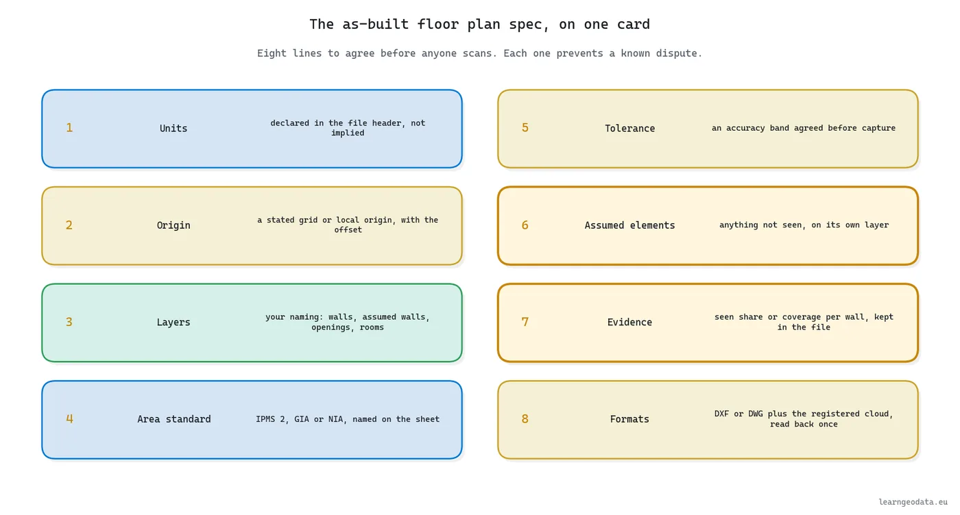
- Units, declared in the file header and on the sheet, never implied by scale
- A coordinate reference or a local origin, with the offset written into the file
- Layer names in your convention: walls, assumed walls, openings, rooms, dimensions
- The floor area standard named on the sheet, for example IPMS 2 or GIA
- A tolerance band agreed in writing before capture, not a figure quoted after
- Assumed or inferred elements on their own layer, drawn differently from measured ones
- Evidence per wall, such as the share of it the scan saw, stored in the file
- Formats: DXF or DWG for the plan, the registered point cloud alongside, and the plan read back once before delivery
The read-back in item 8 sounds fussy until you receive a DXF in millimetres labelled metres. Writing the file takes a library like ezdxf; reopening it to check lengths, layers and units is what catches the expensive mistakes.
🦚 Florent’s Note: Items 6 and 7 cost a surveyor almost nothing if the pipeline already tracks them. On the classroom run, every one of the 4 walls carries its evidence inside the DXF. If a supplier tells you that is impossible, what they are really saying is that their process never recorded it.
From the As-Built Floor Plan to the Next Decision
A floor plan rarely stays a floor plan for long; somebody picks it up and builds the next thing on top of it.
An as-built floor plan is rarely the end product; it is the base layer for the next decision somebody takes about the building. The same walls, rooms and openings feed a BIM model, an accessibility audit, an egress analysis and a renovation quote, so a defect in the plan travels into all four.
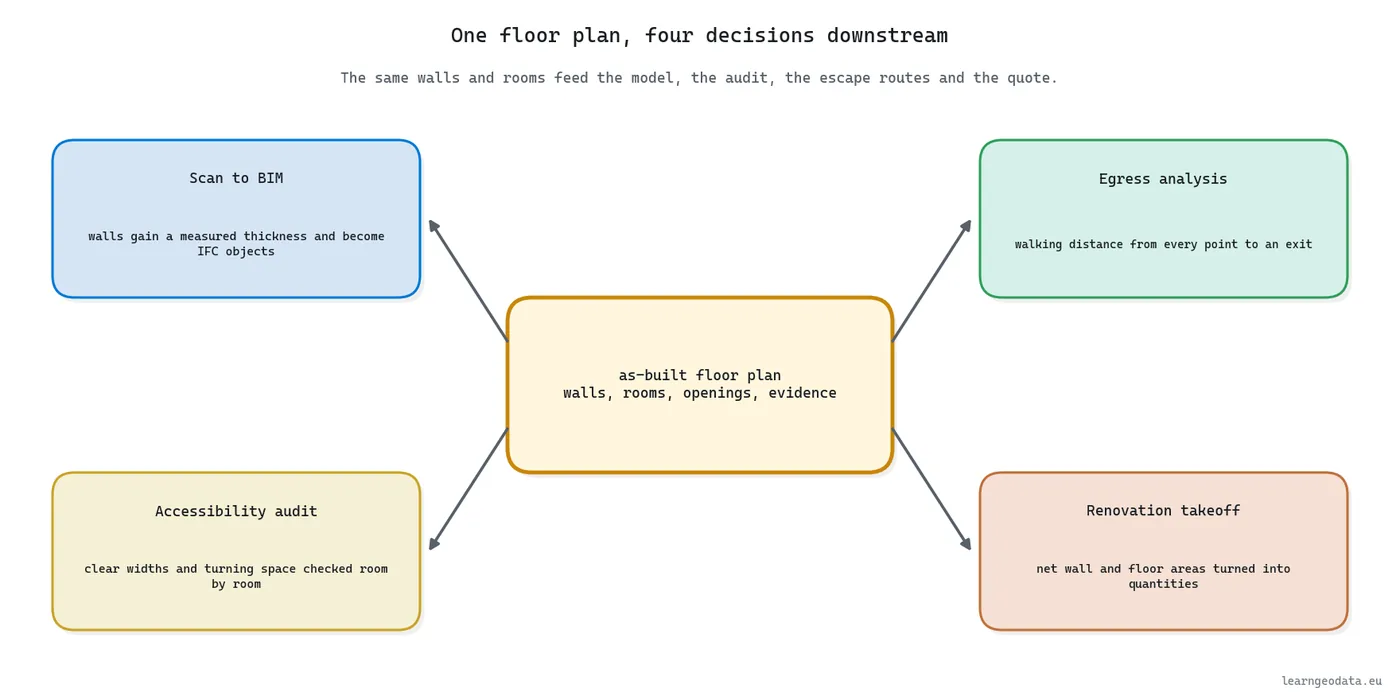
Scan to BIM automation turns the same walls into IFC objects with a measured thickness. A building accessibility audit checks clear widths and turning space room by room. An egress analysis measures walking distance to every exit. And a renovation quantity takeoff turns net wall and floor areas into quantities you can price.
Each of those decisions inherits the plan’s doubts. Route a wheelchair through a stretch that was really a cabinet shadow and the audit fails for a reason born in the floor plan, which is why the assumed layer matters more downstream than on the plan itself.

Under the plan sits segmentation, which decides which points are wall, floor, door or clutter; the point cloud segmentation guide and the indoor shape detection tutorial cover it. The building digital twin guide will put all six use cases side by side.
🦥 Geeky Note: The classroom plan holds one closed room polygon of 55.42 m². The Neurones 3D explainer reports 55.2 m² for the same room. The 0.2 m² gap is the kind of difference two careful methods produce when they draw the boundary on slightly different faces, which is exactly why the area standard has to be named on the sheet.
Own the Floor Plan Pipeline Instead of Ordering It Again
When a team tells me they want this automated by tomorrow, my answer is go for it, on a strong foundation: a half-day audit first, then a semi-automated workflow that fits the team, then full automation on specific parts. Gradual, but it does not take three years.
Owning the floor plan pipeline means you can explain every line on the drawing, rerun it when the building changes, and decide what the code may assume. Ordering a plan gets you a file. Owning the pipeline gets you a file plus the reasons behind it, and the reasons are what a client asks about when an area or a wall is disputed.

Every scanning tool will soon carry a button that produces a floor plan, and I think that is good news. What it changes is where professional value sits: with the person who knows what the button decided, why a wall is dashed, and when to send someone back on site.
Brain-to-Deploy is how I split it. You keep the thinking: which question, which method, which checks, and where “assumed” begins. An engine such as Neurones 3D runs it, and you can drive or extend that engine. Behind the button there is nothing magic, only decisions somebody either recorded or did not.
Start with one room you already have a plan for. Run the scan to floor plan materials on its scan, open the DXF next to the plan you paid for, and see which walls disagree and why. That hour will teach you more about your supplier than any sales meeting. The Medium tutorial walks through the code, and the materials library holds the other kits.
If you would rather watch the whole chain run before you start, I recorded it end to end, from a phone video of a room to its floor plan. The floor plan part starts at 8:22, and the rest of my 3D Tutorials playlist goes deeper on each step.
For the theory under all of this, from classification to indoor modelling, my book 3D Data Science with Python covers the foundations. The 3D Online Course for this series rebuilds the whole chain stage by stage, and the 3D AI Architect program goes well past floor plans and hands you my Python codebase, along with the Neurones Science SDK, for writing tools of your own.
Nolli drew Rome so a reader knew where they could go. So here is my question for you: on the last as-built floor plan you received, could you point to the wall nobody actually saw?
Frequently Asked Questions About As-Built Floor Plans
What is an as-built floor plan?
An as-built floor plan is a measured drawing of a building as it exists today, produced from a survey rather than from design drawings. It shows walls, openings and rooms at a stated cut height, in stated units, with areas measured to a named standard. Surveyors also call it an existing conditions survey or a measured building survey.
How accurate is a floor plan from a 3D scan?
It has two accuracies. Measured accuracy is how well the scanner recorded the surfaces; represented accuracy is how well the drawn lines match them after fitting and squaring, and it is always the larger error. On the classroom run, wall runs fit their points with a median RMS of 7.6 mm, and squaring moved walls by up to 17.7 mm. Agree a tolerance band before capture.
Can a phone with LiDAR produce an as-built floor plan?
A phone with LiDAR produces a fast parametric floor plan that is well suited to space planning. Apple’s RoomPlan, for example, fits walls, doors, windows and furniture as shapes and exports USD or USDZ. It does not report how much of each wall it measured, so for leases, permits or design work, check its key dimensions or use a scanner.
Which floor area standard should an as-built floor plan use?
Use the standard your contract, lease or valuation refers to, and name it on the sheet. IPMS: All Buildings (2023) measures IPMS 2 to the Internal Dominant Face, the surface covering more than 50 per cent of the lowest 2.75 m of a wall section. UK practice still uses GIA and NIA, and North American offices use BOMA.
What should I ask my surveyor to include in an as-built floor plan?
Ask for declared units, a coordinate reference or local origin, your layer names, the named area standard, a tolerance band agreed before capture, assumed elements on their own layer, evidence per wall such as the share the scan saw, and DXF or DWG delivered with the registered point cloud and read back once before handover.
SEO Keywords
as-built floor plan, how to make an as-built floor plan, as-built floor plan from 3D scan, existing conditions survey, measured building survey, floor plan from LiDAR scan, phone LiDAR floor plan accuracy, floor plan area measurement standard, IPMS floor area, scan to floor plan

